I got that chance this new year, working on the submarine project, doing some ridiculous hours and being paid well for them I thought i deserved a late Christmas present :). I started to do A little searching and asking around, then totally by chance one shows up on the expedition boat, I see the guys carry it aboard, gleaming in the sun. I found out where it was and expressed interest in it, before I knew it I was tasked with making some nylon bushes smaller. I think it's a perfect job for the mini mill.
After playing with it for a little bit I decide this is the mill I want :) It is branded as a halfco HM-10 (also known as a seig x2) at hare n Forbes machinery warehouse for $825au inc GST. I ended up buying a tilting vice over the phone that is far too large for this mill, as I am an impatient one I ended up getting it delivered from Adelaide in south Australia with the vice for $920. Which I was happy with, I would have had to wait until march to get one in the Sydney branch because the expedition crew bought the last one in Sydney!
After i got it home and looking at my new toy I thought sweet as. then my mind moved towards what can I put a slot in? Found some plastic and cut a 6mm slot with a ratted old end mill cutter I used to use to hack slots into things with a electric drill or press.
Happy with my form I had another beer or two and looked at it some more and a few beers after that I found my self on eBay looking up CNC stepper drivers. $485au later I was waiting eagerly for my order of a 5 axis stepper driver mach3 compatible with hand controller, 4x stepper motors 156oz/in torque. 3 digital readouts 300mm ea.
Once these arrived I proceeded to look at how it all can be put together. As this is a mini mill and I know how I work, I like to be able to use a machine and not have to program it with gcode every time. So one of the requirements was to maintain the hand controls.
Looking at X and Z Axis I thought this would be easy, so i mounted the motor on the Z micro feed shaft, I mounted a T5 25 tooth 16mm wide pulley, obtained from ausxmods.comfor about $5ea and
matching pulley for the motor 6.3mm centre bore, for a 1:1 ratio, these steppers should be big enough for the job.

Then for the X axis I looked under the bed and saw that the stock leadscrew has a slot in the end of it, so i machined up a 16mm shaft with a 6.3mm hole and grub screw on one end and a 6mm thick tang to fit the slot in the leadscrew. Mount the motor on a piece on 5mm plate so the shafts line up. See the pictures for more details.


The hard part was the Y axis. the plan for this is build a steel frame that will mount the mill on a floor stand later if needed and for now up off the bench about 100-150mm this will allow me to mount the stepper motor directly below the hand crank. To do this I had to remove the leadscrew, machine it down a little on the lathe to take a bearing 6801 to support the screw, this allowed me to remove the stock mount with a retaining plate allowing space for the pulley on the shaft and the handle. This is done now I need to build the frame from steel box tube or 8020 alu profile.


I have a mini ATX motherboard that I have paired with a pci parallel card that has two ports and is EMC2 compatible. This with the stepper board and a breakout board will be mounted in a box 220x220x130mm in size and a scaffold system attached to mount and support a 10" LCD and touch screen and USB keypad in a convenient location that allows the mill to be used. And the screen folded away when it's not in use.
 |
| I have been warned by MattyMatt on #reprap irc freenode server that this board has useless opto isolators and buffering that combine to limit the max step rate and that I should bypass them before it's a problem at least for X and Y axis. |

I figured the ratted and chipped cutter I had wasn't really going to cut the mustard! And decided I should buy some, I looked at hare n Forbes but they were expensive, while probably great quality I thought they were too good to just snap in the mill learning it's limits, so I had me a surf and found my self on eBay again, and ordered 2each of 1-10mm end mill 4flute cutters in 1mm steps for $100au :) I then also bought a new drill bit set for $55au 1-10mm in 0.5mm steps. I have since bought a 8pc set of ball cutters 3mm-16mm. So I have a lot of bits and pieces.
I bought a proxon branded rotary dividing head type thing, that i plan to power for easy helix and gear cutting, for this i need to make a mount for the stepper that allows upright and perpendicular mounting on the bed. This was about $120au I have since found better more applicable units are available for just a little more $$ but will persevere with this unit.

I have designed myself up a quick change collet system that I will be able to control with one stepper motor for the tool carrousel and a air piston to release the tool holder from the collet.
The collet is the largest that my mill will take @16mm shank size. My plan is to make a table that takes 18 tools, each tool will be held by gravity in a wedge shape tray that rotates and follows a cam/groove in the stationary plate. As the wedges follow the cam groove, at the point in the arc that is closer to the head of the mill the holder on the tray extends towards the head, the reason for this is to minimise the amount of lost bed travel that the tool table will consume, this is about 40-50mm from the X axis, not bad for 18 tools if you ask me :)
The fifth axis selects the tool then the x axis moves all the way to the right until the the tool in the tray lines up with the collet. The air piston mounted above the spring loaded arbor bolt gets extended and the collet opens, the head then lowers and takes the tool holder inside the collet then the air piston is released and the tool is ready for use.
To make the tools auto Change (I'm a lazy one did I mention that) I needed to work out a way that the computer could do it for me :)
To do this I bought a long arbor bolt that I cut down to length. Under the top of the arbor bolt I located a spring in the leftover box at All springs in morebank Sydney. The guy there is heaps cool (when he is not busy) and let me have the spring for free :) it's really strong about 30mm round and 150mm long in compressed. I cut the arbor bolt do when I welded a top on the bolt and it was fully screwed into the collet the spring has 5mm of travel left In it, the air piston is located concentric to this. When it extends the tool holder is released from the collet, when it's released the snapping action if the air piston releasing and going up locks the collet and tool holder tight, only requiring about 250lbs of force from the piston. I have a car/4x4 air compressor that makes 10bar of pressure, I have a switch and my mate is making me a 1litre reservoir tank so it doesn't have to run for ever, I will provide an option for shop air if available. Working with 10bar that 147psi I have selected a 40mm diameter piston to give me enough push to over come the spring tension and release the tool.


Now I have to mount the electronics in a box and I am ready to go :) the break out board will have provisions for a coolant pump but that will require a cabinet to keep the crap flying around.


and the pressure switches.
 |
this is the Collet with the tension spring that will form the basis of my tool changer. the above air piston will push the top of the abor down and release the tool, gravity will take it out of the 16mm collet on to the tool tray.
I have since replaced this spring with bellevile spring washers. less whipping and more strength.
also contemplating changing to a 3/4in collet so its compatible with the tormach tooling system.

this is the torsion spring that holds up the head of the mill, this has to go!!! when the head is all the way up this spring does not have enough power to keep the head up that high and will drop, so if you are cnc'ing a gradient if you are not careful the head can fall as much as 3mm into the job farther than you had wanted... replace this with a gas piston from a car boot. about 100lbs should be fine.. too much or too little and you will load up the stepper motor on the Z axis too much

X axis (to the right. ---> )
Y Axis below.
Z axis below to the right.


A Little more details of the ToolChanger.
I have a pneumatic air piston that will press down onto the top of the spring loaded arbor bolt. The piston is rated at 10bar, and is a 40mm diameter piston, if my maths is right i should get about 300lbs of push onto the top of the bolt..
10 bar = 147 psi
to get the power provided by the piston in pounds of force you need to multiply the supply psi by the surface area of the piston in square inches.
i have a 40mm diameter piston, that is 40/25.4= 1.57480 inches in diameter.
the surface area is pi() * (R*R) .. D= 1/2 * R
so pi() * ((1.57480/2) * (1.57480/2)) = 0.62000 * pi() = 1.94779 inches square of surface area.
now if we take that surface area and multiply that by the supply air pressure we get 286lbs of force from the piston imparted onto the arbor bolt.
the spring that i have holding the arbor up is about 250 pounds of force. so the piston should be able to press this down with out too much trouble at all.
The control valves for the piston that i have allow me to power the piston in two directions, as it is a double action piston, this allows me to be able to control the speed at which the piston will react at. i need a slow extension speed so the tool is not smacked out of the collet by the force of the piston hitting the arbor bolt. the release of the spring tension has to be a really quick snapping action to ensure that the tool holder is held firmly in the collet. this snapping action is to replace the action of hitting the collet in to place with a lead faced or soft hammer.
UPDATE: my mate has closed his workshop so this mill has moved back home, as such i no longer have shop air. and will be using a electric linear actuator, 150kg of push 50mm travel and a lever system to give multiplication of approx 7-8 times. giving a total push of 1000kg. onto the bellivile springs.
UPDATE: my mate has closed his workshop so this mill has moved back home, as such i no longer have shop air. and will be using a electric linear actuator, 150kg of push 50mm travel and a lever system to give multiplication of approx 7-8 times. giving a total push of 1000kg. onto the bellivile springs.

the tool carousel will be attached to the left hand side of the bed and will over hang the bed by about 40-50mm, so for the mill to change tools the bed is moved all the way to the right and the is then lowered to meet the tool tray that has been extended by the tool carousel then the air cylinder is extended, this opens the collet and then the head can be lowered onto the tool holder of the tool below. if the tool below the head is not the one we want the 5th axis of the stepper driver board will rotate the carousel so that the desired tool or tray is below the head of the mill..
the tool carousel is constructed in four layers, the first is the support post with stepper motor inside with the shaft poking through a stationary cam plate, past the tool trays and connected to a guide plate. so as the motor turns the guide plate that looks like a circle plate with radial slots in it, and as it does this it rotates the tool trays around the edge, as the trays rotate around the cam plate that is stationary the cam guides follow an elliptical path and three tool trays extend towards the head of the mill, only one of these trays will line up with the collet. the control box on the side of the mills head has been removed to allow for the tool in the position next to the selected one not to be squashed.
this control box will be raised up or moved to the back of the mill.
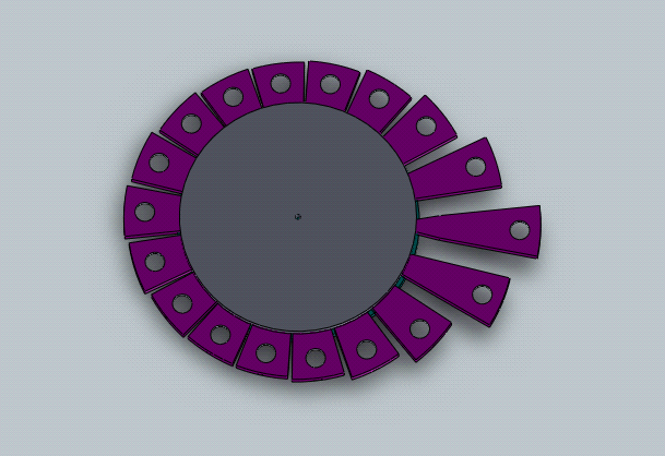
below are two screen grabs from solidworks of my tool changer as it would be installed on the mill you can also see where i want to mount my electronics and touchscreen/keypad.


the guide plate is the blue/green and the tool trays are the purple wedges. in the top picture you can see the grey cam plate that is blow the tool trays.
I have plans to mount a 10inch LCD screen with touchscreen onto a scaffold system that will allow me to move the screen out of the way when its not being used.
so the feature list of this build will eventually be
CNC Mill
10inch lcd with touchscreen
Pentium4 2ghz motherboard with two parallel ports via pci card in mini ATX form factor.
5 Axis of stepper control
coolant pump
job inspection light
Pneumatic automatic 18 slot tool changer
powered dividing head that can be horiz or vert mounted on the bed.
And a ELECTROMAGNETIC Bed clamping system
the electromagnetic bed will be made from 18x 20mm thick slices of 25mm hex bar that has been hollowed out from the top to accept a coil that has been would onto a sewing machine bobbin for a form. this will then be connected to a variable power source that will allow me to dial up any amount of clamping force from nothing upto about 40-50kgs of grip maybe more if my very basic maths that i have done is wrong.. if i dont have 50kg of grip i will keep trying different methods..
to make the coils work better i have decide to make them iron cored, to make the magnetic forces only come out from or go into the top of the be i have decided to make little cups for my coils that i will need to mill a circular ring into the top of each hex peice about 16-18mm deep and about 6-8mm wide. this will accept the coils i will be winding on the sewing machine bobbins.. the coils with then be wired up in some sort of chain or combination of chains so that i get good grip with as little current as possible and lots of grip control. to use this bed i will need to get some clamps of some sort, while i was at the metal suppliers they showed me a 1.5m long 3/4inch square of key steel and they did me a great deal too, it had been there for a while and they let me have it for $100au even. so this will be given to my mate who has access to a nice large industrial milling machine for him to make me some clamping step blocks up, this will make holding work pieces a breeze... i think i will have to go see the guys at the submarine factory and see if i can use their epoxy lab, so i can fill this bed with epoxy and remove all the air bubbles from it.

I am not too sure what the best way will be to wire up this bed, should i have sections that can be turned on and off independently, or should it be all or nothing.. i guess i will make that choice when i have some firm information about the power each of the 18 -20 coils will draw.. i have a roll of 0.2mm wire that i purchased for this mission and some future toys :). i did a little bench test with some 0.5mm thich wire on a coil to see how strong that was and at 3amps i could pick up about 2kgs with it.. so once i go to the smaller wire i will have a lot more turns, i did some quick maths and it says i should have about 15times that power with the new wire and coils..


I have mounted most of the electronics into a box. this includes
A mini ATX motherboard P4 2ghz celeron
Stepper driver interface board
cooling fan.
2 port parallel PCI card connected with a riser cable...
12V 6 amps PSU (for the motherboard and accessories)
24V 15Amp PSU (for Stepper motors)and
the accessories interface board is to have drivers for
Air compressor
Coolant pump
6 endstops
Emergency stop button (that stops both the spindle and the bed.)
a spare user defined input, eg the dividing head zero mark..
UPDATE: going to have to upgrade the PCI parport card to a mesa card so i have enough outputs and inputs for encoders and things.