
A While ago we made a foot control pedal for his tig welding machine, it was a rather simple affair, a box that hinged at the bottom with a spring inside and s few plastic gears on a POT. this was working well but after working with it my mate asked how hard it would be to add a button to half the range of the pedal, after thinking about it for about 5 seconds i found that we could put a fixed 10k resistor in series with the POT and add a bypass switch that allows us to select from 0-100amps and 0-270amps. the pedal that the manufacturer sells retails for $450au. total cost of our pedal is $32 including the new switch. with this extra fine control my mate was able to tack these together with out collapsing the steel into the area that i just milled out.

To make this thing work i require 14 (for now) coils that i can energize and create a magnetic field in the right places in these cups.
When i first thought of this idea i had a search on Ebay for some thing that i could wind the wire onto, i ended up selecting standard sewing machine bobbins. these normally are the ones that go under the foot. Most sewing machines have a feature that allows you to load these with cotton thread with great ease, so i thought i would use my mums sewing machine to load the bobbins but she didnt seem to like the idea of enamel wire running through her machine so while i have been waiting for various parts for various projects i have started yet another project, a Coil winder. i thought it would be advantageous for me to have a way to wind coils in a controlled and repeatable manner. I also like to play with coil guns so it would get a great deal of use for that if it has the right features.
I re-appropriated a old test platform that had a stepper motor hooked up to a M3 threaded rod and a pair of guide rails, i then added three rollers to this to guide the wire to the coil form. one guides the wire from the roll in the up and down vector and the other two cross at 90' to each other to allow me to guide the wire to the left or to the right. My thoughts on the coils i need for my coil gun are varied and rather random, i plan to test differently wound coils to work out whats best. so i have started my coil winder with a simple wind program to start with, this is that the wire is loaded in a random fashion with the stepper motor no moving. these bobbins are only 10mm wide so its not needed. later i plan to add a way to wind coils in either direction, left or right hand rule, be able to wind coils from the left or right only, and control how many turns between switching between left and right feeds.

Here you can see the display of the coil winder I have a few fields on the screen that should allow me to do most of what i want, number of turns per layer. number of layers, wire diameter, and a progressive count of whats going on to the coil form.
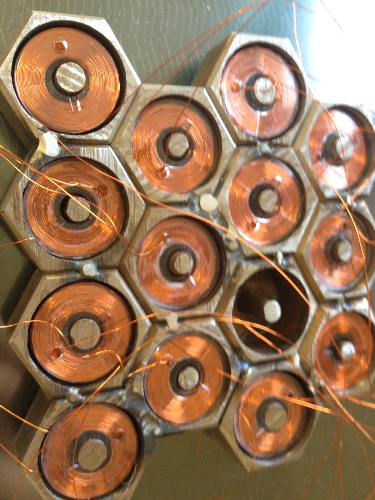
After a few firmware updates and mods and a really annoying hardware bug that turned out to be me, (had a wire one pin to the left from where i thought i had put it, so weird things were happening). Once I started winding coils I found it rather addictive (ask me again after i make 60 of these). I sized up the cups and the coil forms and did a test run on a sacrificial lamb i found that i can get ~880-900 turns onto the bobbins before they start to hang outside the edges. As i was winding i added a few drops of super glue to the coil to help hold them together while i worked on them.
here is a video of the one of the coils being wound onto the form, the first videos shows you the entire setup the second video shows the last stages of winding. there was a big section in the middle that was boring so i chopped it out..

I put heat shrink over the copper wire making sure the conductors were not shorting out to the cups, i placed a bit of kapton tape around the coil itself to protect them from the sharp edges the cups. I then poked the wires through a 3mm hole that i drilled in the bottom of each cup. when i drilled the holes for the wires i made sure they would come out in between the T slots on the Mill Bed. this will allow me to hold it down by drilling some 4mm holes in the center row to some T nuts.

the coils that i ended making have a resistance of about 22ohms each. this kinda works out well. the sacrificial test coil that i made first seemed to cope well with about half an amp of current flowing through it. it did get a little warm after a while (80'c) but that's still well within the specs of the wire. (125'c)
Need to do some testing now. then i will find some epoxy resin that i can pour into/over the coils and cups to provide me with a nice flat surface that i could machine from. but thats only needed if these tests go well.. with each coild taking 6watts each to power up 60 of these could consume some real power. i was reading on the internet the other night that once a coil is energized it only requires 10% of the initiating power to sustain that magnetic filed.. while i am a little skeptical of this claim its worth a test. if i have 13 coils (the astute reader may have noticed already that i knocked a cup off the test bed for other testing..) and I wire them all up in parallel i will end up with 1.6 ohms, If I feed that with 12Volts i should end up with ~ 7 amps. this is quite a bit of power (84watts) if i have to run it at 100% duty cycle. but if i can run that at as little as 10% duty cycle i will only use 8.5 watts.. in theory this will require me to be able to either be able to change the voltage from 12volts to 1.2volts or use PWM. i think PWM is the easiest option a simple 555 timer circuit or a Pic Micro and a Mosfet with a nice big Back EMF clamping diode, should do the job. depending on how many wires i want to use to control the bed i could stagger fire the coils to reduce the load on the PSU. i have many 12v 6Amp PSU's and if i was to stagger fire the coils in groups of four and the 10% Duty Cycle claim turns out to be true i will have no problems at all..
No comments:
Post a Comment