
So at the moment i have all the motors mounted, with their pulleys attached and their respective idle pulleys. The Z axis is all bolted up and the lead screws and motors all turn very easily by hand, i have attached a few spare gears from the old setup to the tops of the motors to allow easy adjustment.
The Y axis bed frame is welded and bolted to the bearings, The same for the X axis, all the axis run really nice and smooth they don't free run when you push them but they all move with a single finger.
Next i have to attach the belts 2 for each X and Z axis. this will hopefully this will keep the carriages nice and square and allow them to roll nice.
I will have to stop at the hardware and get some screw in rubber feet for the base of the frame to keep the Y axis from hitting the motor i have had to mount it about 10mm lower then the bottom of the frame, so at the moment that end of the frame is resting on the motor mount, this will be resolved with some standoff feet. They will also help keep the noise from the table vibrating.
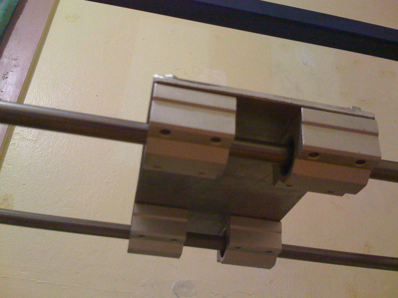


The Z axis was an absolute bitch to install, even though the entire printer was welded pretty much in situ we moved the bearings so the TIG welding didn't cook the goodness out of them, this allowed things to move. It was almost like they were welded under tension, but i know this was not the case. So i persevered, I had to file 1mm clearance extra around the vertical smooth rods as the X frame seemed to have gotten a little wider, this solved half the problem, next i had to bend the bracket that holds the captive nut for Z so the threaded rod would run that little bit smother. Then everything went together really nice, rather annoyed at myself for leaving the belt at my mates work shop. My boss probably thinks its a good thing as i will get a good night sleep instead of working on the printer until i get movement :) so i will go to the workshop tomorrow buy a few mice and feed the snake while i am at it, he is really hungry and then see about attaching the belts, that reminds me i also left the tension springs there too.
Now that i have this much done i am questioning the design of the Triple extruder that i have been planing to use from the old printer, it seems like it going to be rather difficult to install with out it interfering or limiting my print size too much, every way i look at it, it doesn't seem to fit, That was a prototype, and never was intended for long time service, there are too many little things i am not happy with on it, so i may take this opportunity to start the Triple extruder MK2. a lower profile version that may even be print able. to get to use all of the current print bed i am going to have to cut some arches out of the X carriage plate to clear the lead screws and bearings on the Z axis.
No comments:
Post a Comment