Saturday 25 June 2011

Triple extruder gets a work out

Ok so i have been sort of using the triple extruder, when i made the hobbed bolt i mis-placed one of the hobbings and it doesn't align with the idle roller :(

but i have been able to use the other two feed paths of the extruder, i had some fun with nozzles and such but thats another post..

so basically the extruder works as far as i have been able to test, i have to make a little mod to actually have the material change to happen, so far i have had no cam shaft installed. i am starting to think my measurements are wrong..

i am learning how to use solid works so i will draw up what i have and animate the movements to double check things..

 i have two fans one to cool the heat that the entire extruder soaks up and the motors.
 then the smaller one with all the broken blades cools the print for the first layer and maybe bridging when it all works better.
 top down where the filaments run, only one in the middle path in place at the moment
you can also see the dove tail join that hold the extruder in place, and leaves it removable for when i need to work on it, its a bit tight and i have been hitting it to free it up... bad me :(
 here you can see where the cam shaft with a 40tooth gear on it would go in the bearing and across the tension arms/blades the cam shaft has 180' sections taken out @ 90' to each other, this leaves one position where they are all free or one is gripped by the hobbed bolt.

 this is the 20:1 reduction worm drivve that turns the hobbed bolt that is hobbed in three places 10mm apart

here you can see the micro switch that will run on the head of the bolt that has been filed to only have a lump where the cam shaft has all three springs compressed, thus all three filaments are free to be hand loaded or withdrawn if you need to change it is very easy.

when i built this extruder i used all the conservative numbers where i could so this unit is probably a little on the large side, i picked the positions of the fulcrum points by eye and what i thought the motors could handle not what they can handle.. stepper motors are very easy to under estimate... i could probably have gotten away with a smaller motor for the cam shaft, i think once i complete the rebuild i will have a better idea, maybe i will be able to make it printable. then others can enjoy this as well.

i lost a little print area when i installed the triple extruder but it was only 40mm in the X..
i need to replace the hobbed bolt some day soon.. i also need to install stronger springs to get better grip on the filament
you cant see it well but there is a hobbed bolt in there, its driven by the stepper on the right via a 20:1 reduction worm drive. the stepper on the right drives the camshaft the is not installed in this pic, you can see the bearing on the left above the 40 tooth gear on the left, i used two of these gears to move the camshaft up and the motor and its weight down.

one problem i had was that because my hobbed bolt is so far away from my heater barrels my filament bowed out and refused to go down the nozzle. this was easily fixed with a little brass tube from the hobby store, this was pressed into the peek block that i have holding my three nozzles, this extruder could easily be extended to accommodate more  materials with only a 10mm increase in over size in the X axis with my current install but that could also be taken from the Y axis.

my nozzles are made from 5/8th brass threaded rod that i machine down the thread off and wrap with kapton and nichrome wire. i use 100k thermistors. started out with 0.5mm and now want 0.25mm holes.. but thats another story.
 here you can see two nozzles installed but only one wired up with nichrome wire and thermistor.

So far this has been giving me good filament up to about 1000mm/min but i need to install harder springs and better hobbing to get better speeds, once i ditch the lead screws i will have lots more  speed in my movements and needs a extruder that can keep up..

The OverSized bed.

So i over sized my print area by increasing the length of the bed and rails. these ended up being 16mm mild steel rods that i center drilled M5 threads to the ends for mounting. i also cleaned the rails with emery paper to make the rails smoother..


 i then saw a mate that once mentioned he uses lots of plastic round off cuts, and soon i was in possession of  various pieces of 50mm round blocks. some 25mm round blocks and some 75mm blocks. i took the 25mm blocks and drilled a hole 16mm in the center of them then reamed them so they slid on the rails nice.. i made four of these bushes one for each corner of the bed.

the bed was a made by gluing with 5min epoxy these bushes to a piece of perspex that had the four M4 screws mounted in them for the sprint loaded adjusters. the glass bed then had some small perspex lugs made and glued to it.. these lugs had oversized holes and springs glued in place. the lugs were then held down with nuts and washers to allow me to square each corner.


 now this worked great was easy to adjust and was i was happy, now being an impatient  ass i wanted to make something print, as i failed to get the bed up to 110'c i tried the masking tape, this worked quiet well, up to about the 3hour of a 7 hour print of a 40mm cube! then i had to hold it inplace while it finished printing 

Tip: Don't try and print a 40mm cube as a first test, not @100% not @25%... it takes too long..


the result :-
 it has a rounded bottom where it rolled back and forth for hours...
the shorter one on the left was the result when the printer just stopped for an unknown reason.. this gave me hope to try again and got the big full cube out.. this has been the thorn in my side ever since.. all the problems i have had, i look at that sitting on the bench and think why wont it just do that again, at least it was something...

Oh the Glass only bed had a NASTY NASTY ring to it, my Y rails are screwed directly to the bench not actually attached to the A frame, so the bed moving back and forth created a nasty resonance to is, lucky my neighbors cant here it, thank god for double brick interior walls... being in that room made your head hurt.. 

So since this the bed has changed quite a lot.. i sh!ts with the glass only solution and decided to use some of the stepper motor's potential lets make a metal heatbed that will spread the heat evenly, as opposed to the spotty results of the glass only bed..

so i calls up a few mates and i now has  slab of aluminum  6mm thick 480mm x 380mm, on the way home i stop at bunnings hardware and buy me a hacksaw a small bench vice and various bits of aluminum and screws. 

i took the slab and cut some angle so run the length and 3 straps to hold them in place, this then supported the 10mm diameter springs that i found, they were a bit weak so i placed two there to support the weight of the slab. i then cut some PFTE blocks to keep the heat away from the bed itself. i then drilled four M4 holes one in each corner and locked 4 M4 bolts to the lower frame with nuts and loctite, dropped the springs and PFTE blocks over the top then the bed and finally two nuts on top.

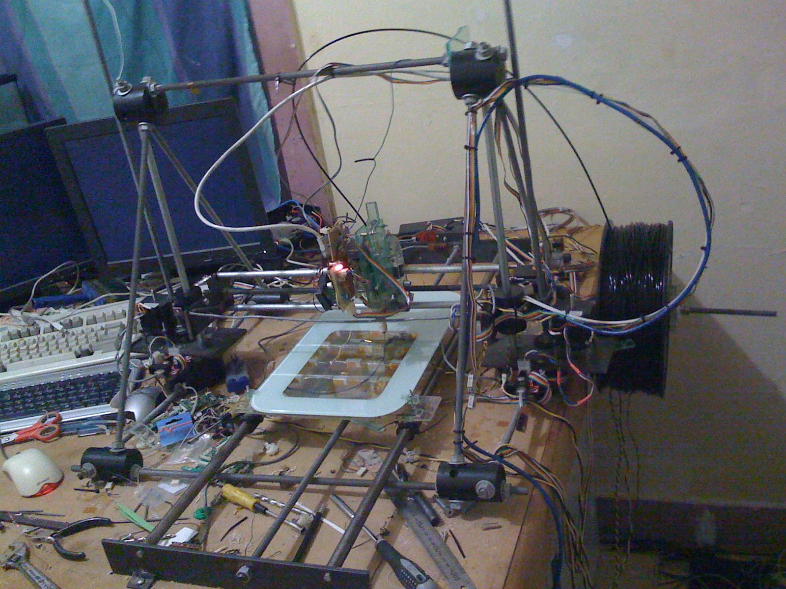
this frame was then attached to the nylon bushes that ran on the rails, it was attached with hose clamps (turns out to be a very bad choice of macguyver technology) these worked well for a while, it was a little tight sliding back and forth so out with some oil to lube things up (castor oil from the hobby shop bought in little drip dispenser ), oiled up it ran nice.. so i then attached this to the lead screw  that ran between the two 16mm rails, the leadscrew had two nuts with a spring between them to reduce the backlash, these nuts were then attached to the center strap under the bed. i used spacer blocks to make up the height difference.. this worked  really nice it even cut the noise down by about 200% it was now bearable to be in that room while it was printing...

 the nylon bushes over time became really tight, i believe it was due to the oils and grease that i used to lube it up, that coupled with lots of heat and a hose clamp around it made the hole in the middle far far too tight on the rails. these had to go... see my post about roller bearing runners.

So i still haven't sorted out the heating, this was a problem i started armed with all the learnings i got from trying to heat the glass bed up that i just have far far too much thermal mass to heat up this slab of metal and a sheet of glass on top of that too!! so i visited my mate who works at a appliance repair shop and tells him my tale of woe with cooking resistors and my fingerprints off several times and he told me he has the solution for me... a 2400 Watt mains Grill element!.. Well my eyes light up when i walked into the room that has all the elements on the wall and started looking around and me being me i picked the worst one.. it was the only one they had, didn't know what it was from, where to get more etc etc, so he picked me the cheapest one they have as they sell these by the box load they will always be avail and would have only been $20 if i didn't know him :) yay... so off to jaycar to buy me a opto coupler and a triac and a little metal box to put it in, as i do i doubled the order expecting to fry at least one of these parts..  and i ended up making a nice little control box that could switch up a total of 2400 watts per channel that could be driven off a 5v logic signal and had it wired up to the heater element, mounted it all up on the desk and was ready to cook steaks at least.. this heated bed has better heat control than my stove ( they are on or off )....
this slab o aluminum is topped off with the same piece of glass that was my glass only bed.

The Heated Print Bed Saga!

So i installed a piece of glass that i re-appropriated from work into my printer as the print surface, it was about 240mm by 310mm by 5mm thick armored glass. ( Woot )


I suspended it over my Y rails with springs and adjusting screws to level it out. this worked great, i turned the screws over so the threaded posts pointed up and an nut and washer pushed down on the bracket this adjusted the bed for leveling and squaring, once  had it square i attempted a print, having not read enough blogs as i should have, my plastic refused to stick to the bed, a quick chat with a few peoples (i think they were peoples, if not they were polite and helpful alien) i found that i needed to heat the bed hotter to get my ABS to stick to it. so a quick search on the web i found me some cheap ceramic power resistors and some thermal double sided tape from jaycar.

And the fun began....


A Quick read of the blogs and wiki i find a number 75'c to get the plastic to stick. so i look at the box of power supplies i have in my junk room, and surface with several 12volt @6.6amps SMPS units, armed with this, my power resistors and my thermal tape i set out to do a heap of ohms laws calculations, i ended up with a spreadsheet that did all the simultaneous equations for the various combinations of 32 1 ohm resistors and 5 PSU's. i ended up at one point with 3 psu's all pushing 5amps plus in to resistor chains, burning my fingers, my desk and even a toe.. but i got it to 77'c!! GOAL.

so i though :( turns out that i didn't read enough of the blog that  i got the 75'c magic number from, and that was for PLA.. turns out ABS needs 110'c so back to jaycar and my junk room, and i have several more attempts to heat a slab of glass up to 110'c.. at onw point i had two 500watt ATX PSU's struggling to give me what i demanded!! all that they had and then some.. i had 4 12volt chains pumping 9 amps each and 2x 5 volt chains pumping 5 amps each... (found that the guy on the net actually knows what he was talking about, you need to load up or use the 5 volt rails on a ATX supply to get the full 12volt Amperage) this was the best i could do and got the glass to 100'c.. Would it be enough to get the ABS to stick...


No... Fail

all i managed to do was to make the resistors glow!! oh and burn my fingers again....

i will try and find a pic of the resistors glowing, but after that test i found that i had destroyed the resistors, they actually split in half.

to control this i simply had all the PSU's running off the one power strip with a switch.. as i couldn't get it hotter than i needed there was no need for the MCU to control it..

Stepper motor Power!!

So i have over sized my copy of mendel http://reprap.org


At the time i started to build my repstrap i thought i may want to print something a bit large, so i decided to extend the print area, after looking at the design of mendel i decided to extend the bed as this would require the least amount of change, extend the drive and rails and bed to suit..


TIP: This worked out ok for me but for a repstrap, Start Small, something that prints smaller things but faster is better than something that is going to print slow but can go big..  testing becomes tedious... very tedious..

As i was saying i over sized my mendel and i figured it needs big motors the motors i ended up selecting the KL23-251-24-B by keiling inc. KL23-251-24-B PDF 
this beast of a stepper has a full Nm of torque to drive my heavy axis
this stepper is being driven by the Gen3 MB2.3 stepper driver. nice stepper controller does the job..

i have used 4 of these steppers one for the Y Axis (bed) one for the X Axis (carriage) Z Axis (rails and carriage).. UPDATE: looking at changing the Z stepper for a bigger one or adding a gearbox to increase the speed of the axis. too fast and i miss steps.
 these are all being driven by their own stepper driver, yes its over kill but MeH thats what this,blog is about Overkill Engineering a solution because my mega bodge solution failed.. one extreme to the next.

 the MDF bed that i attempted to use for testing was about 250mm x 250mm it was held onto nylon bushes with cable ties ( lets just say it didnt sit flat), it was promptly replaced by a piece of glass that came from my work (it was excess.... i didn't steal it.... i swear...) it was nice and flat.. so i mounted that to perspex frame with springs in the corners and M4 screws to make adjusters this worked well, then came time to heat it.. i will leave that saga for another post all of its own..

so i found that you can use masking tape instead of heating your bed so testing of the rig progressed..

The Plan!

Ok
      So i have been playing fighting with a repstrap 3D Printer, due to the relentless offers of assistance from Friends that have the skills and patients the i don't, i have finally come to the conclusion that it needs to be square! solid!

So i have started this blog to let others learn from my efforts (can't call them a mistake if you learn something)

This is what i am starting with.

 My Second extruder, using gen3 Ec2.2 controller, a stepper motor that is far too small, lots of lexan, and plastic gears. 256:1 ratio, 8mm hobbed bolt.
 256:1 gear ratio with the green gears. extra track board with mosfet for heated bed.
 here you can see the spring pushing a clear lever that has a roller bearing idle pulley
 here you can see the height of my dodgy handiwork this corner doesn't sit on the table, if i screw it down the Z axis twists and refuses to travel. not fixing that!

 Extruder version 1 this used a DC geared motor and a piece of plastic ( i wont say what type of plastic it was cuz i don't know, the nozzle didn't stay put) 


 here you can see the filament path was not straight, the idle wheel was not spring loaded the nozzle melted free, i installed a piece of PFTE and the nozzle stayed put, the extruder worked it pumped out 0.55mm filament, only problem was that it only started pumping plastic out at a rate of about 32mm per second, was too fast for my first axis' that i built.

here is the first picture that i took of the rig when i got all the axis moving surprisingly nice. All the axis were driven by a M10 threaded hot dipped zinc plated rod (not the smoothest of finishes) the rods were mounted into mini roller bearings that were pressed into 5mm plates that mounted the stepper motors.